It is another productive year, a big order knocks the door of this. In the beginning, EMEC, our partner from Egypt, after taking time to test our centrifuges, finally come to GN from US suppliers, they purchased about 40 centrifuges in total, and the first one is more than 30units.

Then as we all know, oil price keep going down, market is down. We are holding the project, the project has been delayed is the most often answer we heard from client.
Good news is the Chinese government published the new environmental protection regulations. We need handle the drilling waste. Which makes half of the market live again. While thanks to the seed we have planted, GN have been in study of the vertical cuttings dryer and other driving waste management equipment long time ago. Which makes, again, GN stand in front of all Chinese manufacturers, to supply the high quality waste management products to the local market.
A few dozens vertical cuttings dryer, decanter centrifuges, and dewatering unit have been sent to the Chinese drilling site.
So as the old saying, when the flower blooms outside of the wall, the people inside can smell, the big Chinese contractors finally comes to GN, finally realised and found the best equipment supplier here. One of the best.
Another benefit also thanks to the down time market, more and more Europe or US contractors finally get more and more interested in good quality Chinese suppliers. Since this could be one way to save cost. If can supply same quality with more competitive price, why not keep themselves in the perception of made in China. A lot of people have gave it a try. Maybe you all also should do.
After Baker Hughes choose GN products, more and more big players in the market comes to us, come to our yard, comes to our site, they want to find out what makes Baker feedback that these products even better than US/ EU products.
- Details
-
Published: 23 November 2015
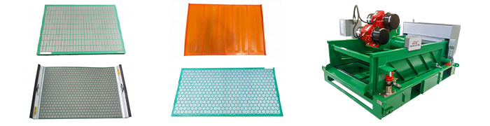
GN Solids Control is a recognized solids control and drilling waste management manufacturer in both home-based and outside China. And Shale Shaker is one of GN Solids Control’s most popular goods in all of GN merchandise line. Each year, GN makes in addition to sells around 250 pieces of GNZS series shale shakers to more than 62 countries and regions of the globe.
GN Shale Shaker Positive aspects:
1 . GN owns twelve patents, most of them are on shale shaker design, and such effective remedies are important to ensure the shaker to present reliable performance without seeping.
2 . GN use Malta Oli brand vibrating engines. For normal models such as GNZS594E and GNZS703E, often the G force for vibrating sex is up to 7. 5, flexible. When talking about High-G blow drying shaker GNZS594HGE-LD, the penis-shaped G-force could reach main. 0.
3. In order to thoroughly stand the high vibrating push from the vibrating motor, often the shale shaker has to be built with a substantial structure. That’s why GNZS series shaker’s deck are made from Stainless Steel.
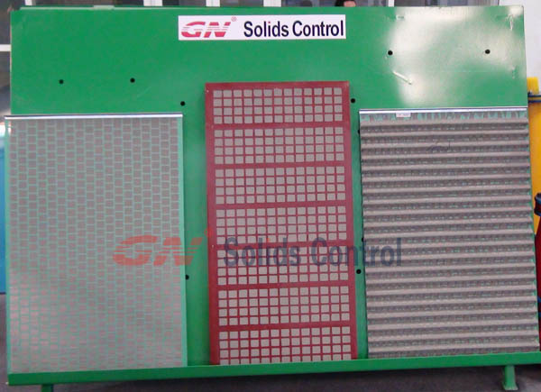
But the good shale shaker is not the only factor to completely show the performance, which is also impacted greatly by the shaker window screens. In order to better control shaker screen’s quality, GN features a separately shaker screen manufacturing plant for supporting GN individual shakers. But since GN displays is very cost-effective, lots of GN clients who already have additional brands’ shakers source window screens from GN. GN would make replacement screen of good good quality and reasonable price with regard to old and new clients, and in addition customizes shaker screens with basis of a MOQ.
The reason why choose GN screens?
- reliable quality and sufficient service life. Because GN Solids Control alone is also shaker manufacturer, GN is more familiar with screens and also knows how to make suitable window screens for shakers.
2 . constantly improving the producing procedure, with proper procedure in addition to methods in making screens, GN screens’ quality is always elevating.
3. good material. GN uses imported glue in addition to based on the mesh center regarding China.
Seeing is thinking, welcome to visit GN and offer trial orders on GN screens.
- Details
-
Published: 18 November 2015
This is an un-complete list of Water Powered DTH Hammer Suppliers.
1. Wassara:
Since Wassara products are water-powered, drilling through water-rich formations is obviously never a problem. But, actually, Wassara hammers go effortlessly through almost any material, from boulders to wood to dense clay, easily, cost-effectively, and quickly.
Wassara water hammers consume up to 80% less energy versus most air-powered drilling waste management systems. Our tools also last far longer due to the very low upward water velocity required.
Because only pure water is used to power our hammers – and no oil is needed for lubrication – no damaging emissions are produced. No oil gets into the groundwater; no dust gets into the air, resulting in a cleaner, safer, work environment.
Water Powered DTH Hammer Definition:
What is DTHand How is it Used? The “Down the Hole†or DTH hammer is used for drilling holes through a wide range of rock types, the variety of which continues to extend well beyond the original conception of early blast hole drilling.
“Down the Hole†refers to where the hammer action occurs when compared to drifter hammers, which hammer on top of the drill string. The DTH hammer piston always makes direct contact with the drill bit, and there is generally no loss of transmitted energy as the hammer drills deeper, as is the case with drifter (top hammer) rigs.
Halco Rock Tools Ltd.
http://www.americawestdrillingsupply.com/Halco/HalcoMain.asp
Halco Rock Tools Ltd. is a world class manufacturer of down the hole (DTH) drilling equipment. Halco pioneered the development and distribution of DTH hammers in the 1950s, and now their precision-engineered range of performance hammers and drill bits is used globally. Predominantly used for mining, DTH is preferred in other applications such as construction, quarrying, formation sampling, and the drilling of water wells.
Cubex Water Actuated DTH Hammer Drills
http://www.advancedconstructiontechniques.com/Cubex-Water-Actuated-DTH-Hammer-Drills.asp
ACT was awarded the Chicagoland Underflow Plan (CUP) McCook Reservoir Grout Test project by the Chicago District, USACE, in 2003. The Specifications required that both “Rotary drilling or rock coring shall only use water as circulating fluid. Percussion drilling shall use water in addition to air as the circulating fluid. Other drilling methods for this portion of the work may be proposed by the Contractor in the RFP for approval by the Government.†After thoroughly review the available Down-the-hole (DTH) drilling techniques, ACT proposed the use of water DTH (W) hammer, the first time adoption and application in the drilling and grouting industry in North American.
- Details
-
Published: 17 November 2015
Hebei GN Solids Control Co., Ltd is leading manufacturer for drilling mud solids control & drilling waste management equipment including vertical cuttings dryer , shale shaker , screw conveyor , screw pump , oilfield shale shaker , mud cleaner , desander and desilter , vacuum degasser , poor boy degasser , decanter centrifuge , mud tank , mud agitator , etc . GN keeps research and develop the best technology to manufacture top quality shaker screens for our clients,.
Recycle the drilling mud that lubricate the drilling bits.
The drilling mud solids control system is for filter away danger solids phase that contain in the drilling mud and reuse the needed solid phase. The task is to keep drilling fluids in stable performance status. There are several machinery that will need to perform the tasks.
The result of consist performance of drilling mud is avoid the blocking and damage of the oil and gas channel. It reduce the well drilling torque and friction drag and reduce the pressure oscillation of the annular air suction. It also increase the velocity of the well drilling, extend life of the drill bit, reduce wear of the equipment.
There are five steps of filtering process that require five solids control machinery that will do
filter screening, degassing the mud, desanding the mud, desilting the mud, centrifuge force separation and demand of weighting up mud. The consist work flow between every solids control equipment use in the whole system is very important. Level one to five level of output of the mud should be matched each other and the interval of separation size should be appropriate and have a certain overlap. The result of the smaller solids which are not filter by the upper can be filter in the next controlled level.
With the development of well drilling technology, drilling fluid solids control system plays an important role in drilling operation. The various kinds of solids control systems function at the same time. Regardless the different kind of the solids control system, it’s basic function will not changed. It is depend on organic combination of mechanical removal equipments, drilling fluid storage tanks and other auxiliary equipments to accomplish the basic function: Recycle the drilling mud that lubricate the drilling bits
- Details
-
Published: 06 November 2015
Nigeria is a beautiful country, though for the first instance, some bad things come to us before thinking about the view, market or anything else. When my colleage is really doing business with Nigerian people, we found some nice person, and always good to cooperate with them, then my colleague said, Im now half Nigerian.
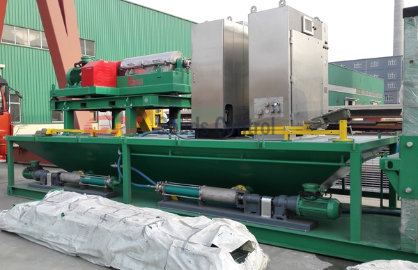
GN Solids Control have done a lot of business with Nigeria companies, mud company, drilling contractor, servsing companies, and so on. This time, we sent 3 sets of drilling waste management system to Nigeria, and now my colleague is there for commissining. Then we get some testing video, pictures, with good result.

This Nigeria client is one of the big drilling contractor in Nigeria, the order is the third order for this client, before this order, client has ever bought shaker screens and 4 decanter centrifuges and one liquid mud plant from GN Solids Control. Right now, GN Solids Control is building another 2 vertical cuttings dryer and a number of screw pump and screw conveyors for the client.
It is modular waste mangement equipment, with certain modification on site, which comes to you in this way, the client lift the centrifuge in a much higher place. The client have 6 rigs, now they are equiping half of their rigs with drilling waste management system.
The list of the waste management equipment include:
3 sets vertical cuttings dryer
6 sets high speed VFD decanter centrifuges
9 screw pumps, with 6 for feeding decanter centrifuges, ther other 3 for flushing the cuttings dryer.
15 screw conveyors for transfer drilling waste to feed the equipment and discharge the solids.
To make sure everything goes perfectlly well on site, we supplly the client layout drawings, and 3D drawings to show all the needed details as instructions. This sweat action do not only save the commissioning hassels, also make everything, communications easier.
- Details
-
Published: 21 September 2015